
Ohm's law experiment
Verify V = IR with a nichrome wire: the circuit, the readings, the V–I graph, resistivity and the viva.
By Rahul Sain · Updated Nov 3, 2026
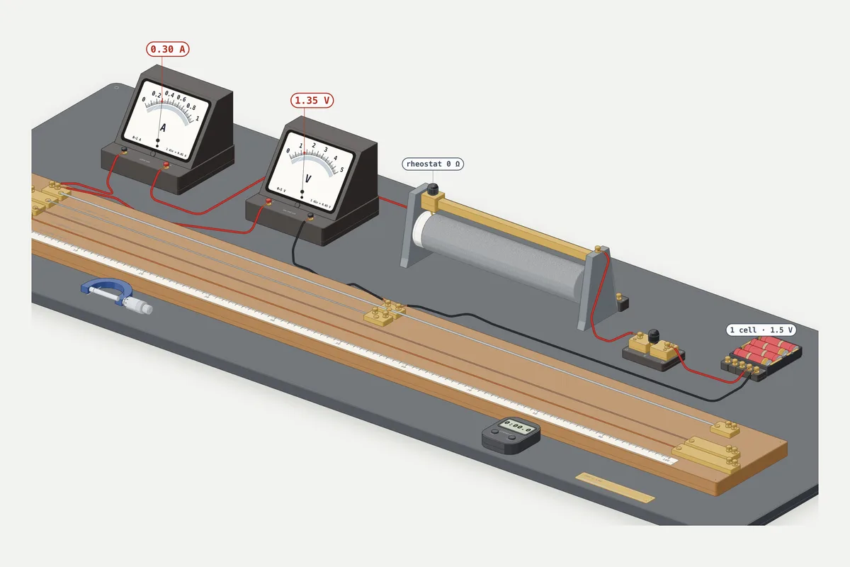 Free 3D labTry it in the 3D labCurrent and resistance: take the readings yourself, free, no sign-in needed.
To verify Ohm's law, you connect a nichrome wire to a battery through an ammeter (in series) and put a voltmeter across the wire (in parallel). Then you change the current, with more cells or a rheostat, and note the current I and the voltage V each time. If V/I stays about the same and the V–I graph is a straight line through the origin, the wire obeys Ohm's law, and the slope of that line is its resistance.
This guide covers the CBSE Class 10 practical from aim to viva, and the Class 12 version, where the same graph gives the wire's resistivity. Every number is worked in full, so you can check your own file against it.
Quick answers
- Ohm's law: the potential difference across a metallic wire is directly proportional to the current through it, provided its temperature stays the same. V = IR.
- Ammeter: in series with the wire. Voltmeter: in parallel, across the wire.
- V–I graph: a straight line through the origin. With V on the y-axis, slope = R.
- Typical result: a 50 cm nichrome wire, 0.40 mm thick, gives V/I of about 4.4 Ω.
- Class 12: resistivity ρ = RA/l. For nichrome you should get about 1.1 × 10⁻⁶ Ω m.
- Most important precaution: take the plug out of the key between readings so the wire does not heat up.
What Ohm's law says
In NCERT Class 10 Science, Chapter 11 Electricity, Ohm's law reads: the potential difference V across the ends of a metallic wire is directly proportional to the current flowing through it, provided its temperature remains the same (NCERT Science X, Ch. 11). So V ∝ I, and V/I = R, a constant called the resistance. Its SI unit is the ohm (Ω): 1 Ω = 1 V / 1 A.
Two limits matter in the lab and in the viva:
- Temperature must stay constant. Resistance changes with temperature, which is why you switch the current off between readings.
- Not everything is ohmic. The NCERT Class 12 Physics chapter Current Electricity lists cases where V is not proportional to I. A diode is one: reverse the voltage and it does not pass the same current the other way (NCERT Physics XII, Ch. 3, §3.6). A filament lamp is another: its filament heats up as the current rises, its resistance goes up, and its V–I graph curves.
Nichrome suits this experiment: the same chapter notes that its resistivity depends only weakly on temperature.
Where this experiment is in your syllabus
- CBSE Class 10 (2026-27): Practical 4 in the Science curriculum: "Studying the dependence of potential difference (V) across a resistor on the current (I) passing through it and determine its resistance. Also plotting a graph between V and I." (CBSE Science X 2026-27)
- NCERT Class 10: Activity 11.1 (Chapter 11, Reprint 2026-27) uses a nichrome wire XY "of length, say 0.5 m", an ammeter, a voltmeter and four 1.5 V cells.
- CBSE Class 12 (2026-27): Section A, Experiment 1: "To determine resistivity of two / three wires by plotting a graph for potential difference versus current." (CBSE Physics XI–XII 2026-27)
- ICSE Class 10 (2027): Practical 11: verify Ohm's law with a simple circuit, draw a graph and obtain the slope (CISCE ICSE Physics 2027).
Aim
To study how the potential difference (V) across a nichrome wire depends on the current (I) through it, to find its resistance, and to plot a graph between V and I.
Apparatus
- A nichrome wire XY, 50 cm long (0.40 mm thick in the readings below)
- Four 1.5 V cells (or a battery eliminator)
- An ammeter, 0–1 A
- A voltmeter, 0–5 V
- A plug key
- A rheostat (0–20 Ω used here)
- Connecting wires and a piece of sandpaper
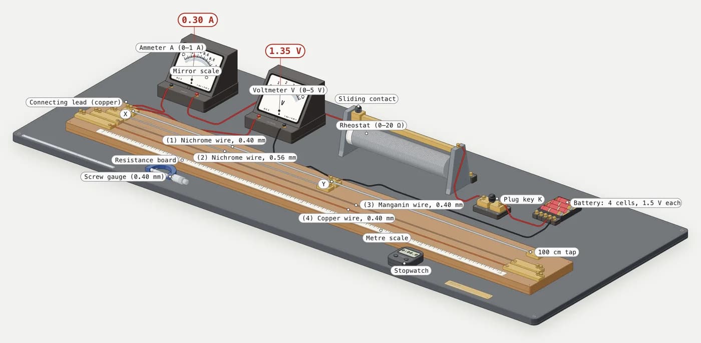
The circuit, part by part
Follow the loop from the battery's + terminal:
- Plug key (K), in series, to open and close the circuit.
- Rheostat, in series, to change the current without changing the battery.
- Ammeter (A), in series, its + terminal towards the battery's + side.
- Nichrome wire XY, the resistor under test, then back to the battery's − terminal.
- Voltmeter (V), outside the main loop, with its terminals on X and Y. Its + terminal goes to the end nearer the battery's + side.
This is the arrangement of NCERT Fig. 11.2, "Electric circuit for studying Ohm's law", with a rheostat added.
Why the ammeter goes in series and the voltmeter in parallel
NCERT states that an ammeter "is always connected in series" and a voltmeter "is always connected in parallel across the points between which the potential difference is to be measured" (NCERT Science X, Ch. 11). The reasons:
- An ammeter measures the current through the wire, so that current must pass through it. Its very low resistance barely changes the current.
- A voltmeter measures the potential difference across the wire, so it touches both ends. Its very high resistance draws almost no current.
Swap them and it fails: a voltmeter in series blocks the current, and an ammeter in parallel short-circuits the wire and can be damaged.
Least count: how to read the meters
The least count is the smallest value one division of the scale stands for:
Least count = range ÷ number of divisions
For the meters used here, each scale has 100 divisions:
- Ammeter, 0–1 A: 1 A ÷ 100 = 0.01 A per division.
- Voltmeter, 0–5 V: 5 V ÷ 100 = 0.05 V per division.
To read a meter, count the divisions to the pointer and multiply by the least count:
- Ammeter pointer on the 55th division: 55 × 0.01 = 0.55 A.
- Voltmeter pointer on the 48th division: 48 × 0.05 = 2.40 V.
Your school's meters may differ, so work out the least count from your own and write it in your file. Before closing the circuit, check both pointers sit on zero; if not, note the zero error and correct every reading. Read with your eye straight above the pointer (on a mirror scale, line the pointer up with its reflection) to avoid parallax.
Procedure
- Clean the wire ends with sandpaper.
- Set up the circuit with the plug out of the key, and check both meters' zero.
- With cells (NCERT Activity 11.1): connect one cell. Put the plug in, read the ammeter (I) and voltmeter (V), then take the plug out.
- Repeat with two, three and four cells. Take the plug out after each pair of readings.
- With the rheostat (CBSE practical): connect all four cells. Set the rheostat to its highest resistance, put the plug in and note I and V. Take the plug out.
- Lower the rheostat's resistance in steps (20, 15, 10 and 5 Ω here) and note I and V at each step, taking the plug out each time.
- Calculate V/I for every reading.
- Plot V against I and draw the best straight line.
Take at least five readings for a good graph.
Observation table
Least count of ammeter = 0.01 A. Least count of voltmeter = 0.05 V. Zero error: nil.
Table 1: changing the number of cells (NCERT Activity 11.1)
| S. No. | Number of cells | Current I (A) | Potential difference V (V) | R = V/I (Ω) |
|---|---|---|---|---|
| 1 | 1 | 0.30 | 1.35 | 4.50 |
| 2 | 2 | 0.55 | 2.40 | 4.36 |
| 3 | 3 | 0.76 | 3.30 | 4.34 |
| 4 | 4 | 0.93 | 4.10 | 4.41 |
Table 2: four cells, changing the rheostat
| S. No. | Rheostat (Ω) | Current I (A) | Potential difference V (V) | R = V/I (Ω) |
|---|---|---|---|---|
| 5 | 20 | 0.23 | 1.00 | 4.35 |
| 6 | 15 | 0.28 | 1.25 | 4.46 |
| 7 | 10 | 0.37 | 1.60 | 4.32 |
| 8 | 5 | 0.53 | 2.30 | 4.34 |
These readings are what a 50 cm nichrome wire of diameter 0.40 mm gives (true resistance about 4.38 Ω), rounded to each meter's least count.
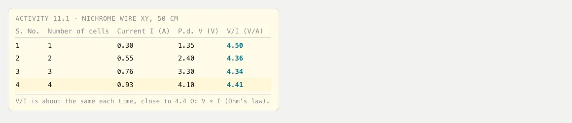
Four cells give 6.0 V, yet the voltmeter shows only 4.10 V across the wire. The rest is lost in the cells' internal resistance and the leads. That is normal: Ohm's law is about the V across the wire, not the battery's label.
Calculation
Each R in the tables is V ÷ I, rounded to two decimals: for example 1.35 ÷ 0.30 = 4.50 Ω and 2.30 ÷ 0.53 = 4.34 Ω.
Sum = 4.50 + 4.36 + 4.34 + 4.41 + 4.35 + 4.46 + 4.32 + 4.34 = 35.08 Ω
Mean R = 35.08 ÷ 8 = 4.385 Ω ≈ 4.39 Ω
Check: every value lies between 4.32 Ω and 4.50 Ω, at most 2.6% from the mean ((4.50 − 4.385) ÷ 4.385). That is the spread rounding to the least count produces, and NCERT says you will find "approximately the same value" of V/I each time. So V ∝ I.
The first row is furthest off because one ammeter division (0.01 A) is 3.3% of 0.30 A but only 1.1% of 0.93 A. Small currents give the least precise V/I.
Plotting the V–I graph
- Axes: I on the x-axis, V on the y-axis, as in NCERT Fig. 11.3. Then the slope is R.
- Scale: use most of the sheet. Here, 1 cm = 0.1 A (0 to 1.0 A) and 1 cm = 0.5 V (0 to 5.0 V).
- Plot all eight points and draw one straight line through the origin, as close to all of them as possible. Do not join the dots.
- Why through the origin: if no current flows, there is no potential difference across the wire. V = IR gives V = 0 when I = 0.
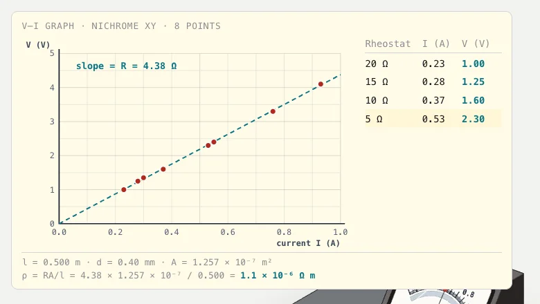
Slope. Take two points far apart on the line, not data points. Here the line passes through (0.20 A, 0.88 V) and (0.80 A, 3.50 V):
Slope = ΔV ÷ ΔI = (3.50 − 0.88) ÷ (0.80 − 0.20) = 2.62 ÷ 0.60 = 4.37 Ω
That agrees with the mean of the V/I values (4.39 Ω) to within 0.5%. A best-fit line through the origin for all eight points, slope = ΣVI ÷ ΣI², gives 10.437 ÷ 2.3841 = 4.38 Ω, the same answer.
Result
- The ratio V/I is nearly constant, and the V–I graph is a straight line through the origin. So the potential difference across the nichrome wire is directly proportional to the current through it: Ohm's law is verified.
- Resistance of the wire: mean of V/I = 4.39 Ω. From the slope of the graph = 4.37 Ω.
Class 12: resistivity from the V–I graph
In Class 12 you do the same experiment, then go one step further. The resistance of a uniform wire is R = ρl/A, where l is its length, A its cross-section area, and ρ (rho) the resistivity of the material. Resistivity is a property of the material, not of the wire's size. Its SI unit is the ohm metre (Ω m) (NCERT Science X, Ch. 11). Rearranged:
ρ = RA / l, with A = πr² = πd²/4
R comes from the graph's slope, l from a metre scale, and the diameter d from a screw gauge, measured at several places in two perpendicular directions and averaged.
Worked example
Wire: nichrome, l = 50.0 cm = 0.500 m, d = 0.40 mm, R = 4.38 Ω (slope).
- Radius r = 0.40 mm ÷ 2 = 0.20 mm = 2.0 × 10⁻⁴ m
- Area A = πr² = 3.1416 × (2.0 × 10⁻⁴)² = 3.1416 × 4.0 × 10⁻⁸ = 1.257 × 10⁻⁷ m²
- ρ = RA / l = (4.38 Ω × 1.257 × 10⁻⁷ m²) ÷ 0.500 m = 5.505 × 10⁻⁷ Ω m² ÷ 0.500 m = 1.10 × 10⁻⁶ Ω m
Units check: Ω × m² ÷ m = Ω m. Correct.
Resistance per cm, which some boards ask for = 4.38 Ω ÷ 50 cm = 0.088 Ω/cm.
CBSE asks for two or three wires. With 100 cm of the same nichrome you get about R = 8.71 Ω, twice the 50 cm value since R ∝ l. Then ρ = 8.71 × 1.257 × 10⁻⁷ ÷ 1.00 = 1.09 × 10⁻⁶ Ω m: different R, same ρ.
Check the power of ten. NCERT Class 10 Table 11.2 lists nichrome as 100 × 10⁻⁶ Ω m and manganin as 44 × 10⁻⁶ Ω m. Standard data tables give nichrome as 100 × 10⁻⁸ Ω m (1.00 × 10⁻⁶ Ω m) and manganin as about 48 × 10⁻⁸ Ω m (HyperPhysics resistivity table). Nichrome alloys vary a little, so a result close to 1.0–1.1 × 10⁻⁶ Ω m is good.
Precautions
- Take the plug out of the key after every reading. NCERT's own note says: always take out the key after measuring the current. A current left on heats the wire, its resistance rises, and the "constant temperature" condition fails.
- Never connect the cells' terminals directly to each other or let bare leads touch. A short circuit drains the cells fast and makes them and the wires hot.
- The wire can get warm. At four cells the wire takes about 4.10 V × 0.93 A = 3.8 W. Don't hold it while current flows.
- Use only the cells or battery eliminator your lab provides. Never use mains electricity for this experiment.
- Meter + terminals towards the battery's + side, or the pointer moves backwards.
- Start the rheostat at its highest resistance and keep currents inside the meter's range.
- Clean and tighten every contact; a loose one makes readings jump.
Common mistakes and sources of error
- Voltmeter across the wrong points: it goes across XY only, not the battery or wire-plus-ammeter.
- Leaving the current on: the wire heats and later V/I values creep upward.
- Using the battery's 6 V as V, or taking the slope from data points instead of the drawn line.
- Sources of error: parallax, rounding to the least count (worst at small currents), zero error, loose contacts, the wire warming, and non-uniform thickness (which matters for ρ).
Viva questions with answers
- State Ohm's law. The potential difference across a metallic conductor is directly proportional to the current through it, provided its temperature stays the same.
- Why is the ammeter connected in series? It must carry the same current as the wire. Its resistance is very low, so it hardly changes that current.
- Why is the voltmeter connected in parallel? It measures the potential difference between two points, so it is connected across them. Its high resistance means it draws almost no current.
- What does the slope of the V–I graph give? With V on the y-axis, the slope is the resistance R. With I on the y-axis, it is 1/R.
- What does a rheostat do here? It changes the resistance in the circuit, and so the current, without changing the battery. That lets you take many readings.
- Why take the plug out between readings? So the wire does not heat up. Heating changes its resistance, and Ohm's law needs a constant temperature.
- Why is nichrome used? It has a high resistivity and its resistance changes very little with temperature. NCERT also notes that alloys like it do not oxidise readily at high temperatures.
- Name a non-ohmic device. A filament lamp (its resistance rises as it heats) or a diode (it conducts much more one way than the other).
- If the wire's length is doubled, what happens to R and ρ? R doubles. ρ stays the same, because it depends on the material and temperature, not the size.
- What is the SI unit of resistivity? The ohm metre (Ω m).
Try it in 3D
Student Intelligence has a free 3D version of this bench at /labs/ohms-law. It follows NCERT Activity 11.1: a 50 cm nichrome wire XY, four 1.5 V cells, a plug key, a 0–20 Ω rheostat, an ammeter (0–1 A, 0.01 A per division) and a voltmeter (0–5 V, 0.05 V per division).
You can change the number of cells, set the rheostat to 0, 5, 10, 15 or 20 Ω, put the plug in or take it out, and record each reading. The readings fill the Activity 11.1 table, plot the V–I graph with its slope, and give ρ = RA/l. You can also swap in a longer or thicker nichrome wire, a manganin wire, or a copper wire, which sends the ammeter off its scale. The bench, its controls, and a short quiz and flashcards are free without an account. Doing the experiment step by step with the voice tutor needs a free sign-in.
FAQ
What is the expected result of the Ohm's law experiment?
V/I comes out nearly the same in every reading, and the V–I graph is a straight line through the origin. That shows V ∝ I. The value of the constant is the wire's resistance, for example about 4.4 Ω for 50 cm of 0.40 mm nichrome.
Why do my V/I values differ slightly?
Each reading is rounded to the meter's least count, and small currents suffer most. A spread of a few percent is normal. A steady rise in V/I through the readings usually means the wire is heating up.
Does Ohm's law apply to a bulb?
Not over its working range. A bulb's filament gets much hotter as the current rises, so its resistance rises and the graph curves. Ohm's law holds for a metallic conductor at constant temperature.
What is the difference between resistance and resistivity?
Resistance (Ω) belongs to a particular wire and depends on its length, thickness and material. Resistivity (Ω m) belongs to the material only. Two nichrome wires of different length have different R but the same ρ.
Practising this before your practical? Student Intelligence's free 3D lab lets you take the readings and draw the graph yourself.
Sources
- NCERT. Science, Textbook for Class X, Chapter 11 "Electricity" (Reprint 2026-27): Activity 11.1, Fig. 11.2, Ohm's law, Eq. 11.5–11.10, Activity 11.2 note on the plug key, Table 11.2. https://ncert.nic.in/textbook/pdf/jesc111.pdf
- NCERT. Physics, Part I, Textbook for Class XII, Chapter 3 "Current Electricity" (Reprint 2026-27): §3.4 Ohm's law, §3.6 Limitations of Ohm's law, temperature dependence of nichrome. https://ncert.nic.in/textbook/pdf/leph103.pdf
- CBSE. Curriculum 2026-27, Science, Class X: Unit IV and Practical 4. https://cbseacademic.nic.in/web_material/CurriculumMain27/SecPart1/Science_SecP1_2026-27.pdf
- CBSE. Curriculum 2026-27, Physics, Classes XI–XII: Class XII Unit II and Section A Experiment 1. https://cbseacademic.nic.in/web_material/CurriculumMain27/SecPart2/Physics_SecP2_2026-27.pdf
- CISCE. ICSE 2027 Physics syllabus: Ohm's law and Practical 11. https://cisce.org/wp-content/uploads/2025/03/10.-Physics.pdf
- Nave, R. HyperPhysics: resistivity table (Ω m at 20 °C). Georgia State University. https://hyperphysics.gsu.edu/hbase/Tables/rstiv.html